WEAR: Wearable ECG Activity Recordings
This databset is described in (Please cite this publication when referencing this material):
Qingxue Zhang, Drew A. Hall, Roozbeh Jafari. An ECG Dataset Representing Real-world Signal Characteristics for Wearable Computers,IEEE Biomedical Circuits and Systems Conference (BioCAS), October 22-24, 2015, Atlanta, Georgia, USA
Introduction:
Wearable ECG-based heart health monitoring computers are playing an increasingly important role in our daily lives. The ECG signal acquired are determined by several variations on the signal acquisition path, like human activities, various sources of interference (baseline wander, motion artifacts, and power line interference), signal path variations (electrode types, coupling methods, and common-mode rejection methods), and electrode placements (wrist and chest). All of these factors should be carefully considered when designing a wearable ECG monitoring. We provide insights into the real-world wearable ECG signal to give recommendations on the low power design of the analog front-end (AFE) and provide the opportunity to the algorithm researchers to consider real-world data in their algorithm design and evaluation.

Major considerations in the signal acquisition path:
We have considered numerous variations in the acquisition system such as human activities, electrode type (wet vs. dry), coupling (AC vs. DC), and placement (wrist vs. chest) in addition to the common-mode rejection (CMR) method, as shown in the following figure:

Use cases:
The dataset now includes 52 use cases for each of the 5 subjects, for a total of 260 recordings with duration of 90 to 210 seconds each. More recordings will be added in future. Each experiment is named as X_Y_Z where X ∈ {P, D} (P: patch-based electrode, D: dry electrode), Y ∈ {D, A, CL, OL} (D: DC coupling, A: AC coupling, CL: closed-loop CMR, OL: open-loop CMR), Z ∈ {W, C1, C2} (W: wrist, C1: chest-1, C2: chest-2). The measured dynamic range of the ECG signal without (HB DR_max) or with (Signal DR_max) interferences (baseline wander, motion artifacts or power line interference) are also shown in the following table, and their ratio illustrates the enlargement of the dynamic range due to interferences.
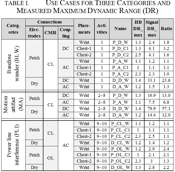
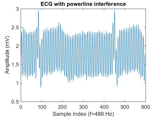
- 10 Activities: 1) sitting; 2) drinking coffee; 3) typing the keyboard; 4) pressing and releasing the signal electrode; 5-6) walking at 1 and 3 mph; 7-8) running at 5 and 7 mph; 9-10) sitting, 0.6 and 6 feet to the power line.
- CL/OL CMR: closed-loop/open-loop common-mode rejection.
- HB DR_max: maximum peak-to-peak voltage of the clean heartbeat (HB) among 5 subjects. HB DR_max in category MA and PLI reuses that in category BLW.
- Signal DR_max: maximum peak-to-peak voltage of the signal after digital filtering among 5 subjects.
- Ratio: equals to ‘Signal DR_max / HB DR_max’.
Links to download the dataset:
For each subject, there are 3 categories: baseline wander, motion artifact and powerline interference.
- Category I: baseline wander. There is one session with different electrode, coupling methods and placements, including 8 use cases.
- session 1001: no motion and far from powerline
- Category II: motion artifact. There are 4 sessions, corresponding to 4 combinations of electrode types and coupling methods. Each session includes 7 use cases.
- session 2001: patch-based electrode, DC coupling
- session 2002: patch-based electrode, AC coupling
- session 2003: dry electrode, DC coupling
- session 2004: dry electrode, AC coupling
- Category III: powerline interference. There are 2 sessions, corresponding to closed-loop and open-loop common mode rejection configurations. Each session includes 8 use cases.
- session 3001: closed loop-common mode rejection
- session 3002: open loop-common mode rejection